Spanning Tree Protocol: STP in a nutsell. Configuration & Explained.

The Spanning Tree Protocol (STP) is a network protocol that guarantees that every bridged Ethernet local area network has a loop-free topology.
Dr. Radia Perlman, a distinguished engineer at Sun Microsystems, invented STP. Dr. Perlman came up with a way for bridges to achieve Layer 2 routing utopia: redundant and loop-free service. Consider a spanning tree to be a tree that the bridge holds in memory for fault-tolerant and optimised data forwarding.
ON THIS PAGE: Spanning Tree Protocol: STP in a nutsell. Configuration & Explained.
-
In a nutshell, the spanning tree.
-
Using a spanning tree to exclude loops
-
Configuration of Spanning Tree Protocol
-
Getting over the disadvantages of Spanning trees
-
Spanning tree alternatives: TRILL and NPB
-
Spanning Tree Protocol
-
Setting up STP settings
-
How to Use the GUI:
In a nutshell, the spanning tree.[ps2id id='In a nutshell, the spanning tree.' target=''/]
- STP is a technique for preventing loops in an Ethernet network through blocking connections. If active links crash, blocked links may be reactivated.
- The conceptual centre of a spanning tree is the root bridge, which sees all network traffic.
- When the network switches, spanning tree recalculations are done automatically, however they trigger a brief network outage.
- Newer protocols, such as TRILL, avoid loops while maintaining connections operational that would otherwise be interrupted by STP.
Using a spanning tree to exclude loops[ps2id id='Using a spanning tree to exclude loops' target=''/]
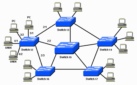
Since there is nothing at Layer 2 to avoid a loop if the switches are linked in a loop without STP, each switch will infinitely repeat the first transmitted packet heard.
By blocking one or more of the connections, STP avoids loops. If one of the active connections fails, the system may fall back to a previously blocked connection. The topology that a spanning tree can see determines how it selects which connection to use.
The concept behind a spanning tree topology is that bridges will find a loop-free subset of the topology: the tree. By covering the whole LAN, STP ensures that there is adequate bandwidth to access any part of the network.
Configuration of Spanning Tree Protocol[ps2id id='Configuration of Spanning Tree Protocol' target=''/]

When bridges are first linked to the network or when the topology changes, they can use the spanning tree algorithm.
When a bridge receives a "configuration packet," a kind of BPDU (bridge protocol data unit), it starts the destructive spanning tree algorithm. The first step is to choose a "root bridge" from which all data can flood.
Tip: The root bridge on Cisco hardware is usually the computer with the lowest MAC address. It's better to programme the root bridge manually because it's the oldest and most likely slowest unit.
The next move is for each bridge to decide the shortest route to the root bridge in order to determine how to reach the "middle." On each LAN, a second election is held to choose the assigned bridge, or the bridge that is nearest to the root bridge. Packets from the LAN would be sent to the root bridge by the assigned bridge.
The last move in setting up an individual bridge is to choose a root port. Simply put, this is "the port from which I transfer data to the root bridge."
Notice that whenever a port is configured as "ignore," any port on a bridge, even those connecting to endpoints, can participate in the spanning tree.
The other attached devices can comply with a reconfiguration BPDU sent by a newly connected bridge. For 30-50 seconds, all traffic is halted as a spanning tree measurement is performed.
Rapid STP[ps2id id='Rapid STP' target=''/]
Rapid spanning tree, an updated variant of the spanning tree algorithm that prevents outages, was first introduced in 2001 by a few vendors. It's backwards compatible with older computers that still know the old spanning tree algorithm, and it cuts the 30-50 second downtime period in most situations to under ten seconds, so try it if you can.
Notice that RSTP operates by inserting a backup port and an alternate port. Rather than actively waiting for the network to merge, these ports are enabled to join the forwarding state right away.
VLANs and PVST[ps2id id='VLANs and PVST' target=''/]
If one of the physical ties happens to be a VLAN trunk, VLANs and PVST STP will trigger issues. Since there is only one spanning tree, the link to the VLAN trunk will need to be blocked. As a consequence, a single VLAN's access to the remainder of its LAN can be lost. Allow per-VLAN spanning trees to solve this problem (PVST).
When PVST is allowed, each VLAN on the bridge will have its own spanning tree case. If a trunk connection contains VLANs 1, 2, and 3, it will determine that VLANs 1 and 2 can not use that direction, but VLAN 3 should.
Getting over the disadvantages of Spanning trees[ps2id id='Getting over the disadvantages of Spanning trees' target=''/]
One of the disadvantages of STP is that, even though there are several physical or equal-cost multiple paths between nodes in your network, all of your traffic would move through a single route identified by a spanning tree. The advantage is that traffic circles are stopped, but there is a price to pay. By restricting traffic to this one-of-a-kind path, other, and often more convenient, routes are blocked.
That means your network's maximum potential capability would never be realised. (As discussed above, you may use several simultaneous spanning trees for different VLANs, but traffic in any given VLAN would still not be able to use all of your network capacity.)
Spanning tree alternatives: TRILL and NPB[ps2id id='Spanning tree alternatives: TRILL and NPB' target=''/]
This was understandable in the past, but with the growing usage of virtualization technologies in many data centres, a more robust and stable routing infrastructure is needed to accommodate the very large I/O demands of virtualized environments.
TRILL and NPB are two tree-spanning alternatives.
TRILL (Transparent Interconnection of Several Links) is a network specification for routing protocols that:
- Instead of STP, shortest route routing protocols are included.
- Since it operates at Layer 2, it can be used by protocols like FCoE.
- Multihopping experiences are supported.
- Uses connections that would otherwise be prevented and works with every network topology.
- It's possible to use it in conjunction with STP.
TRILL's key advantage is that it frees up network bandwidth that might otherwise go unused (to avoid routing loops) if you used STP, enabling Ethernet frames to follow the shortest route to their target. This translates to better network capacity efficiency and a lower cost-to-benefit ratio.
These advantages are particularly valuable in data centres that operate cloud storage networks. TRILL is therefore more robust than STP since it recovers better in the case of a hardware breakdown.
Spanning Tree Protocol[ps2id id='Spanning Tree Protocol' target=''/]
The Switchdevice is compatible with the following:
- The Spanning Tree Protocol is a link-management protocol that guarantees a layer-2 network architecture that is free of loops.
- The IEEE 802.1Q standard defines the Multiple Spanning Tree Protocol (MSTP).
- Rapid Spanning Tree Protocol (RSTP) for each VLAN (also known as Rapid PVST or RPVST); RSTP is specified in the IEEE 802.1w standard.
- The following topics are covered in this chapter:
- MSTP overview and jargon
- Configuration of MSTP
- Interactions that occur outside of the MSTP area
Looking at the MSTP setup[ps2id id='Looking at the MSTP setup' target=''/]
Interoperability with per-VLAN RSTP (rapid PVST+ or RPVST+) is supported.
MSTP overview and jargon[ps2id id='MSTP overview and jargon' target=''/]
MSTP allows numerous spanning tree instances, each of which transports traffic for one or more VLANs (the mapping of VLANs to instances is configurable).
MSTP is backwards compatible with both STP and the Rapid Spanning Tree Protocol (RSTP). A layer-2 network may include switches that support MSTP, STP, or RSTP.
MSTP is based on RSTP, thus it offers rapid network fault recovery and convergence times.
Regions[ps2id id='Regions' target=''/]
A region is a collection of linked switches with the same multiple spanning tree (MST) configuration (region name, MST revision number, and VLAN-to-instance mapping). A network can have as many regions as it wants. Because the VLAN-to-instance mapping differs across regions, they are independent of one another.
In a region, the FortiSwitch unit can host up to 15 MST instances. Each MST instance may be assigned to several VLANs. Each switch in the area must have the same VLAN-to-case mapping.
The MST area serves as a single link between neighboring MST regions and non-MST STPs.
IST[ps2id id='IST' target=''/]
Instance 0 is a unique instance known as the internal spanning-tree instance (IST). IST is a spanning tree that links all of a region's MST switches. The IST is allocated to all VLANs.
The only instance that exchanges bridge protocol data units is IST (BPDUs). Each MSTP instance is represented by its own BPDU in the MSTP BPDU (captured in an M-record). M-records are appended to the end of a standard RSTP BPDU. This enables the MSTP area to communicate with a RSTP switch.
CST[ps2id id='CST' target=''/]
The common spanning tree (CST) links all MST regions as well as any instances of STP or RSTP operating in the network.
Message age and hop count[ps2id id='Message age and hop count' target=''/]
Within a region, MST does not utilize the BPDU message age. Within the area, the message-age and maximum-age fields in the BPDU are transmitted unaltered.
A hop-count method is employed inside the area to age out the BPDU. The IST root transmits BPDUs with a hop count of the maximum number of hops. Each time the BPDU is transmitted, the hop count is decremented. The switch discards the BPDU and ages out the information on the receiving port if the hop count approaches zero.
STP port functions[ps2id id='STP port functions' target=''/]
Each switch port is assigned a port role by STP. The role is determined by configuration, topology, the relative location of the port in the topology, and other factors. The port transmits or receives STP BPDUs and passes or stops data traffic according on the port role. Here's a quick rundown of each STP port role:
- Designated.One specified port is chosen for each connection (segment). The port nearest to the root bridge is the chosen port. This port transmits BPDUs across the connection (segment) and routes traffic to the root bridge. Each designated port in a STP-converged network is in the STP forwarding state.
- Root.The bridge can only have one root port. The root port is the connection to the root bridge. The root port in a STP-converged network is in the STP forwarding state.
- Alternate ports connect to the root bridge but are not root ports. The STP blocking status is maintained on the alternative ports.
- Backup—This is a particular situation in which two or more switches' ports are linked together (either directly or through shared media). In this instance, one port is designated as primary, while the other ports serve as backup (in the STP blocking state).
STP loop security[ps2id id='STP loop security' target=''/]
The STP loop-protection function adds further safeguards against layer-2 forwarding loops (STP loops). When a STP blocking port in a redundant topology incorrectly transitions to the forwarding state, a STP loop is formed.
Only if it continues to receive BPDU messages does a port stay in the blocking state. If it no longer receives BPDUs (for example, owing to a unidirectional connection failure), the blocking port (alternative or backup port) is identified and switches to a forwarding state. This scenario may result in a loop in a duplicate topology.
If the loop-protection feature is activated on a port, it is required to stay in the blocking state even if the port no longer receives BPDU messages. It will not enter the forwarding state and will not forward any user traffic.
The loop-protection function is activated per port. Fortinet advises you to activate loop protection on any non-designated ports (all root, alternate, and backup ports).
Root guard STP[ps2id id='Root guard STP' target=''/]
Root guard prevents the interface that has it enabled from being the route to root. When superior BPDUs are enabled on an interface, they are ignored or discarded. Without the use of root guard, every STP-enabled switch retains the potential to redirect the path to root. Rerouting may lead your network to send significant volumes of traffic across unsecured connections, or it may enable a malicious or misconfigured device to pose a security concern by routing core traffic via an insecure device for packet capture or inspection. By activating root guard on several interfaces, you may enforce the chosen network topology by creating a perimeter around your current routes to root.
STP BPDU security[ps2id id='STP BPDU security' target=''/]
BPDU guard, like root guard, preserves the intended network architecture. When BPDU guard is activated on STP edge ports, any BPDUs received cause the ports to go down for a certain amount of time. The network edge is enforced, and no BPDUs are transmitted.
Configuration of MSTP[ps2id id='Configuration of MSTP' target=''/]
- The following stages are involved in MSTP configuration:
- Set STP parameters that are shared by all MST instances.
- Set up parameters that are unique to each MST instance.
Set up loop protection on all undesignated ports.
Setting up STP settings[ps2id id='Setting up STP settings' target=''/]
Some STP parameters (region name and MST revision number, for example) are shared by all MST instances. Protocol timings are also shared by all instances since only the IST sends out BPDUs.
How to Use the GUI:[ps2id id='How to Use the GUI:' target=''/]
- Navigate to the Switch > STP > Settings menu.
- Update the parameters as shown in the table below.
- To save the settings, click Update.
| Settings | Guidelines |
|---|---|
| Disabled | Disables MSTP for this switch. |
| Flood BPDU Packets | Select this checkbox if you want the STP packets arriving at any port to pass through the switch without being processed. If you do not select this checkbox, STP packets arriving at any port are blocked.This option is only available when MSTP is disabled. |
| Enabled | Enables MSTP for this switch. |
| Name | Region name. All switches in the MST region must have the identical name. |
| Revision | The MSTP revision number. All switches in the region must have the same revision number.The range of values is 0 to 65535.The default value is 0. |
| Hello Time (Seconds) | Hello time is how often (in seconds) that the switch sends out a BPDU.The range of values is 1 to 10.The default value is 2. |
| Forward Time (Seconds) | Forward time is how long (in seconds) a port will spend in the listening-and-learning state before transitioning to forwarding state.The range of values is 4 to 30.The default value is 15. |
| Max Age (Seconds) | The maximum age before the switch considers the received BPDU information on a port to be expired. Max-age is used when interworking with switches outside the region.The range of values is 6 to 40.The default value is 20. |
| Max Hops | Maximum hops is used inside the MST region. Hop count is decremented each time the BPDU is forwarded. If max-hops reaches zero, the switch discards the BPDU and ages out the information on the receiving port.The range of values is 1 to 40.The default value is 20. |
Max Hops is a man of many talents.
If you select this option, STP packets arriving at any port will travel through the switch without being processed. STP packets arriving at any port are banned if this option is not selected.
Within the MST area, maximum hops is utilized. Each time the BPDU is transmitted, the hop count is decremented. If the maximum number of hops approaches zero, the switch discards the BPDU and ages out the information on the receiving port.
The possible values range from 1 to 40.
The default setting is 20.
Using the Command Line Interface (CLI):
switch stp configuration
set floodenable | flooddisable
set the time ahead
set the hello-time
set the maximum age
set the maximum number of hops
mclag-stp-bpdu | both | single
set the name
make a revision
change the status to enable | disable
end
If you are interested in more in-depth tech tutorial, bookmark my website to don't loose anything and stay tuned

Comments
Post a Comment